
Plumbing & Wiring Details..
(All layouts & circuits are under development and subject to change without notice)
| Name | Description |
|
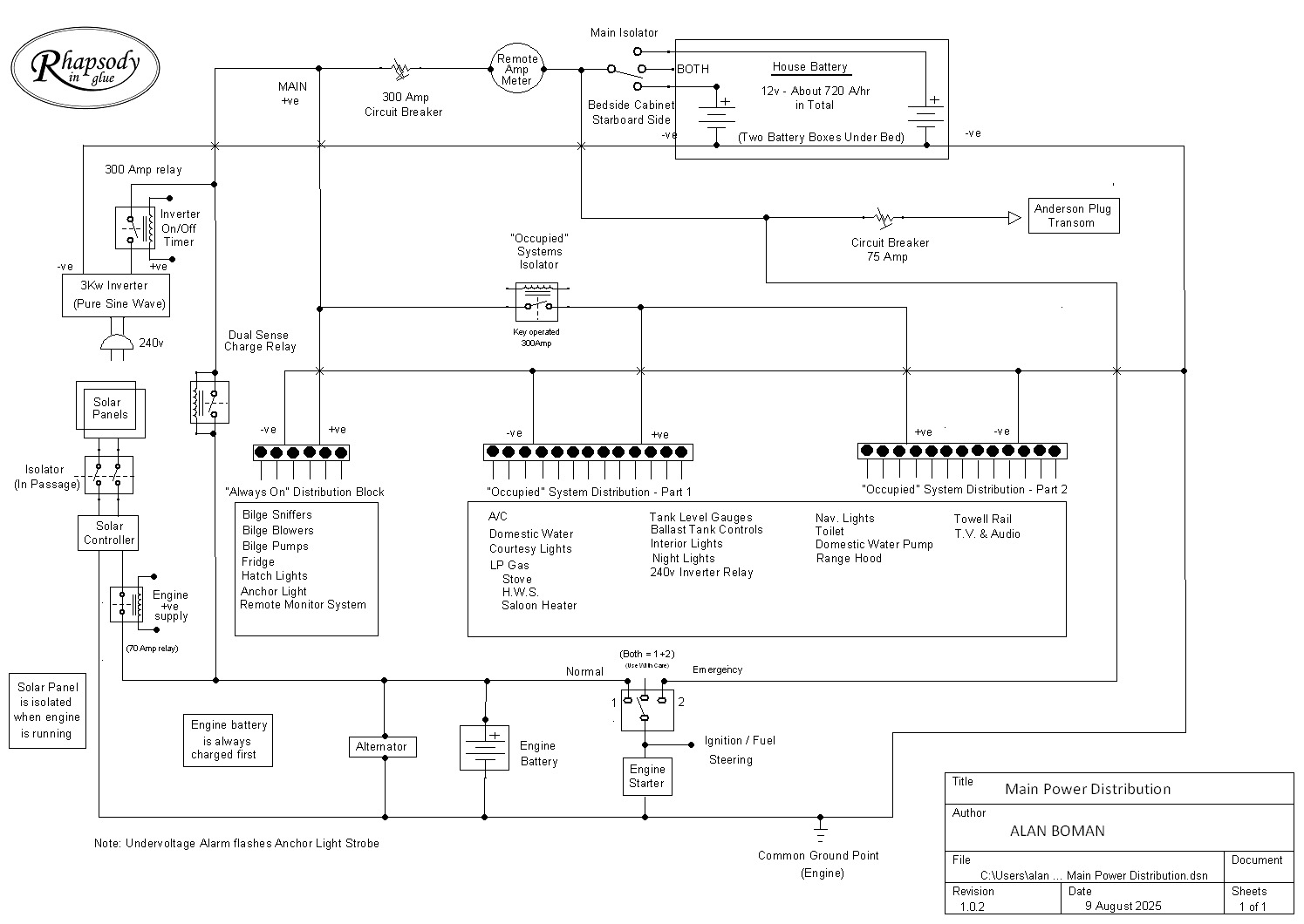
The main distribution of 12volt cabling around the boat with circuit breakers and switches. There are two battery banks one for "engine' and one for "house". All can be charged from either the engine or from solar panels. There is no provision for connection to shore power. A 240volt pure sine wave inverter is included for micro wave etc.
|
|
|
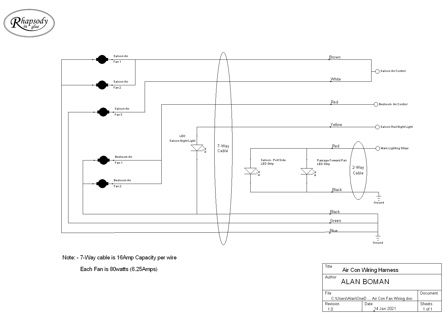
The A/C fan system has five fans powered by two cables fed through a conduit in the back of the wardrobe. One is a 7-way and one is a 2-way. Connections and colour codes are shown. Some cables are doubled because of the current drawn by the fans vs the current capacity of the wire
|
|
| A/C Control Wiring |
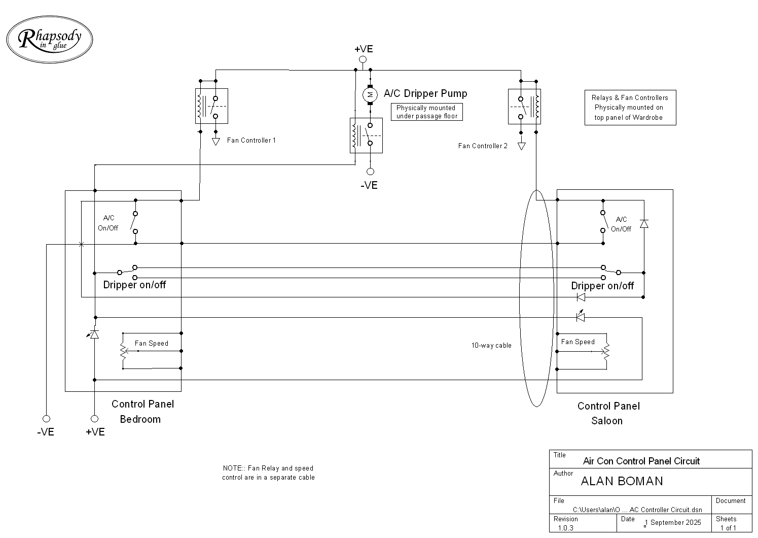
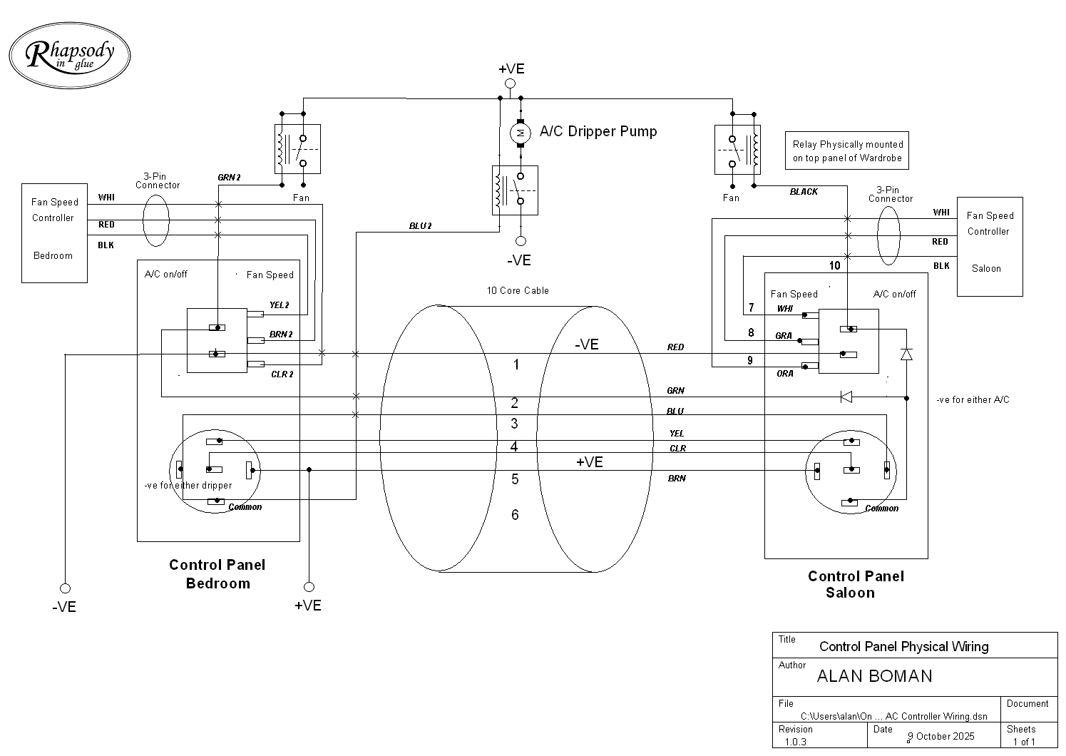
The A/C control system has two switch panels. One in the saloon and one adjacent to the bedroom.They are interconnected by a 10-way cable, which is then connected to the on/off relays and speed controllers in the top of the wardrobe.
|
|
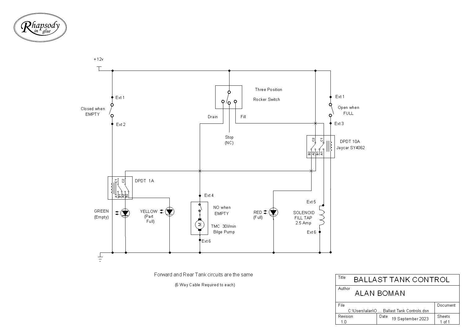
There are two ballast tanks. One forward under the Galley floor and one Aft, under the bed. Each can be "Full", "Empty" or somwhere in between. Indicator lights are provided and switches to fill or empty the tanks as well
|
|
|
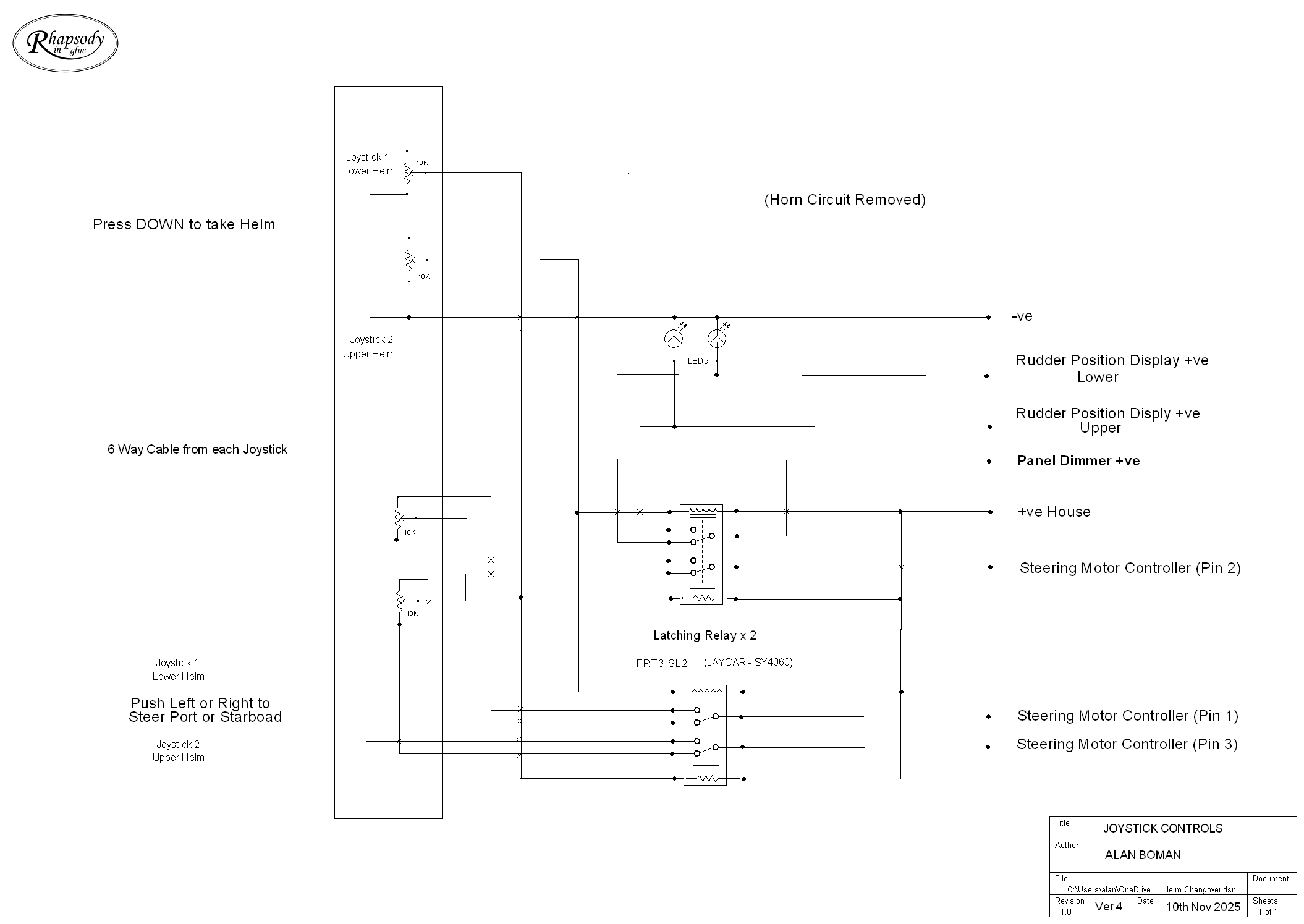
There are two helm controls. One in
the saloon and one on the flybridge. Each consists of a four-way
joystick. Left and right movements steer the boat to Port
and Starboard respectively. |
|
|
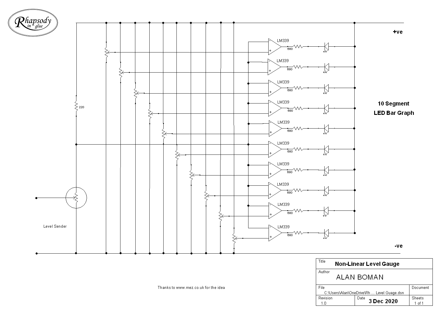
There are three tanks that have level gauges - black water, drinking water and main fuel. (The removable fuel tanks are not included). Given that the tanks have an irregular shape, a non-linear to linear coversion is required to accurately drive bar graph displays.
|
|
|
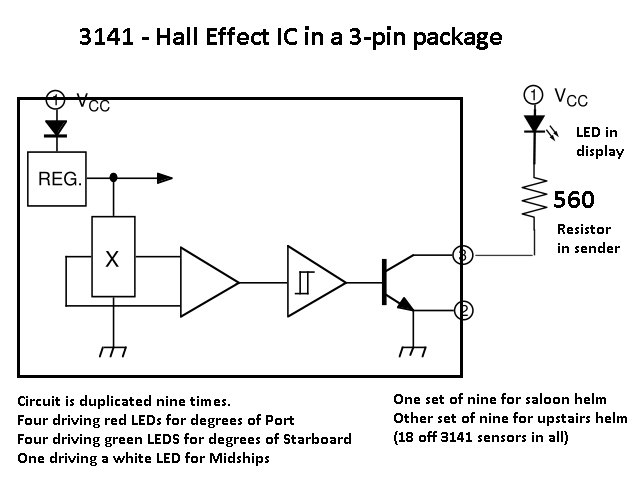
The angle of the rudder, at any given moment, is detected by a set of Hall Effect ICs positioned above a magnet mounted on the rudder quadrant. There are four red LEDs for degrees of Port helm and four green LEDs for Starboard. A white LED indicates Midships. A second complete set of LEDs duplicates the display for the Fly Bridge helm position.
|
|
|
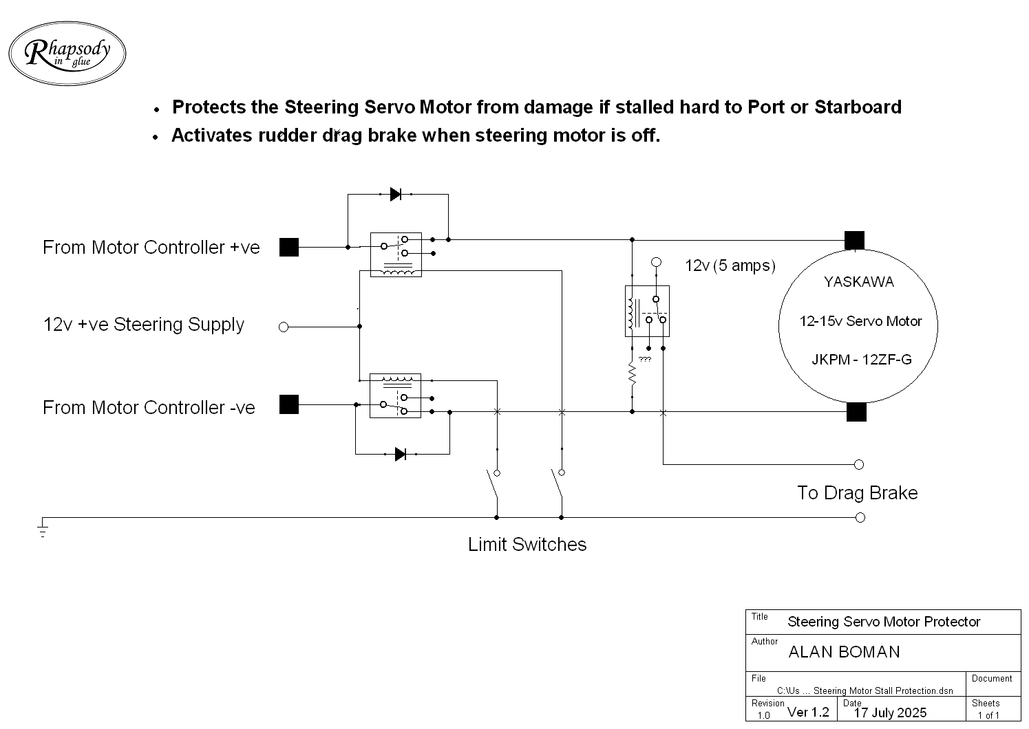
If the rudder is stalled hard to Port or Starboard, the power to the servo motor is cut and is only allowed to be re-applied in the non-stalled direction.
The rudder drag brake is applied whenever the servo motor is inactive to avoid immediate self-centrering.
|
|
|
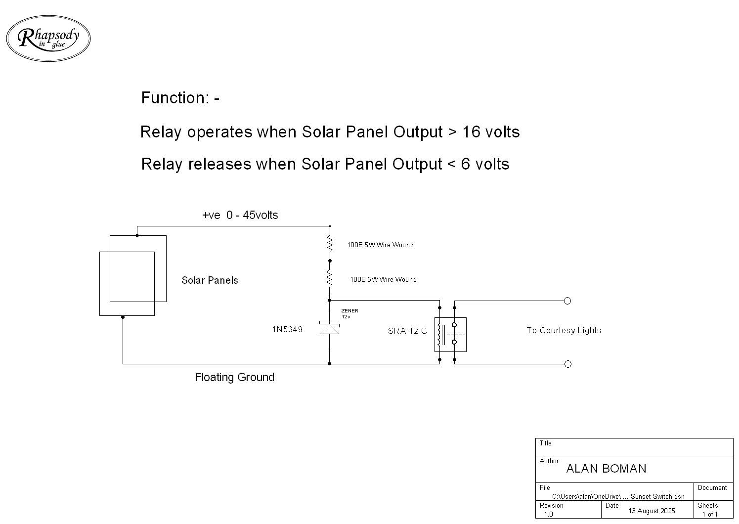
When the output of the solar panels rises above about 16 volts, the relay calls and opens the contacts to turn the courtesy lights off. At dusk, when the solar panel voltage drops below about 6 volts, the relay drops out and the courtesy lights illuminate the stairs |
|
|
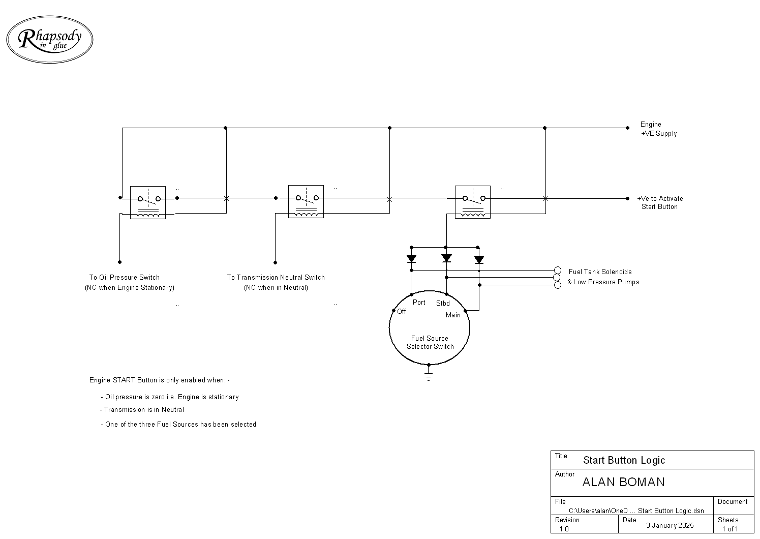
The engine Start button is only enabled once the power to the engine is switched on, plus three other conditions. The first is that the engine is not already running. This is done by monitoring the oil pressure switch, which will be closed when the engine is stationary. The second is that the gearbox is in neutral and the third is that one of the three fuel tanks has been selected. |
|
|
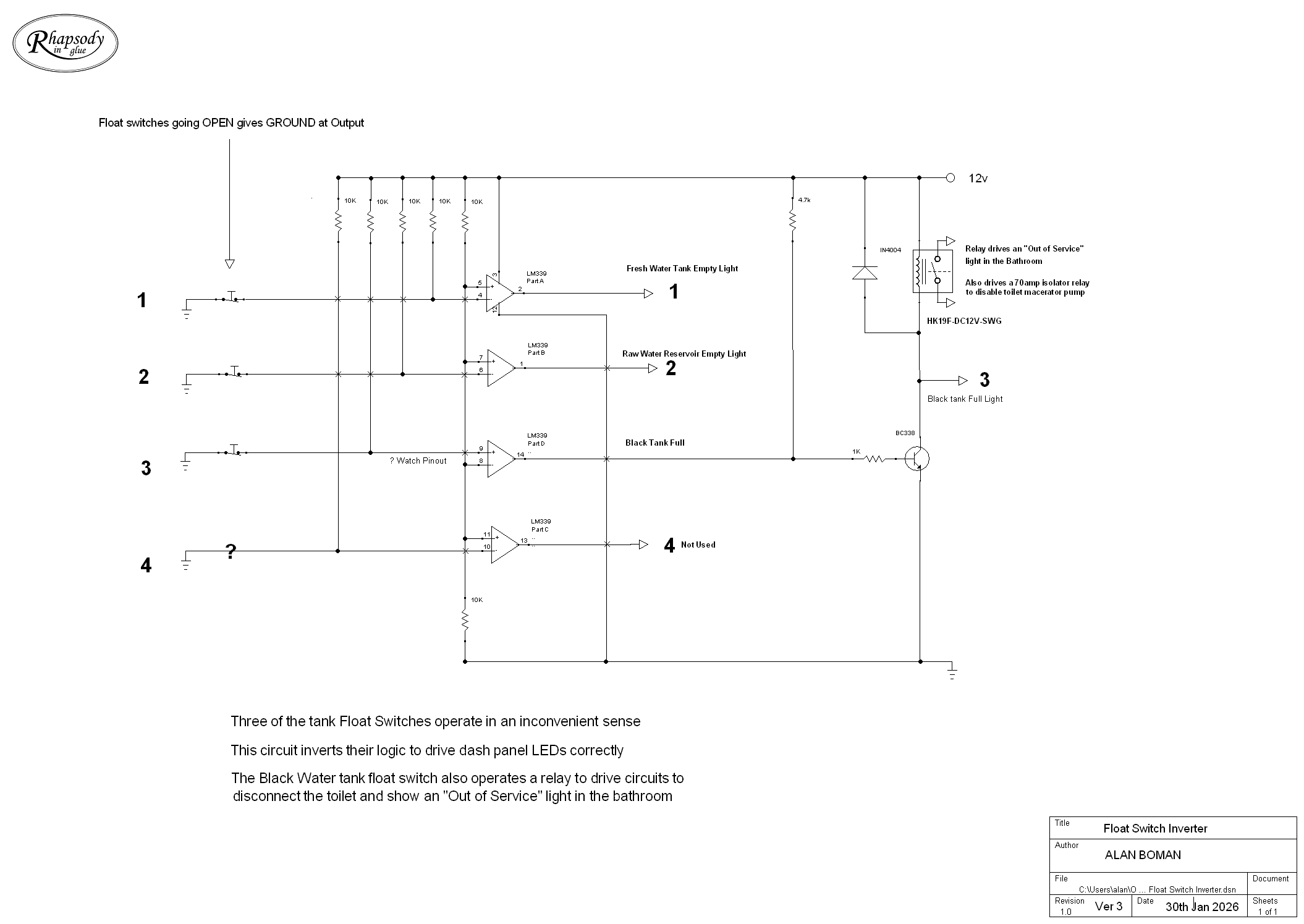
Various tanks have float switches fitted to check for full/empty conditions and to light LEDs on the Dashboard accordingly. Three of them work the wrong way, logically, so this circuit inverts their operation. The black tank has additional circuits to drive to disable the toilet etc. A relay is used to provide the necessary current. |
|
|
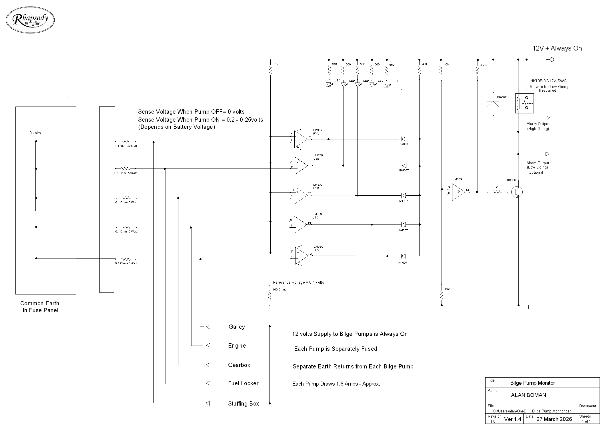
There are five automatic, individually fused, bilge pumps. One each for the Galley, Engine, Gearbox, Petrol tank locker and Stuffing Box. If any pump is activated, it has to show an alarm light, illuminate the Blue strobe light on the roof, and send an alert via the remote communications system. |
|
|
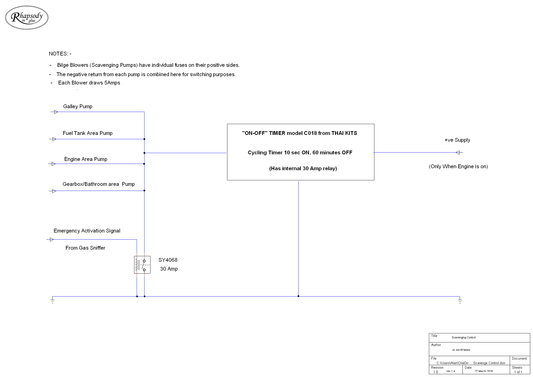
There are four individually fused Bilge Blowers used to clear fumes from the bilges. One each for the Galley, Engine, Petrol Tank and Gearbox areas, including under the bathroom floor. They are controlled by a cyclic timer such that, anytime the engine is switched on, they come on for 10 seconds and then rest for one hour, and repeat. They can also be activated by the Petrol/Gas Fumes detector at anytime, even when the boat is unattended. |